Seeing a Utility Network
With Omnfrequency Receivers
Background
In underground utility locating, each frequency used tells a different story about an underground network. Instead of frequencies that are “right” or “wrong” for a given locate, any frequency can contribute to the larger picture of what’s happening underground. What lower frequencies reveal about the location of nearby utilities is different from what higher frequencies can show.
Throughout the profession’s history, various transmitters have been designed to address this reality of frequency selection. With these transmitters the operator applies alternating current to the utility using multiple frequencies, and traces each frequency separately using the receiver. This method of locating can reduce time spent in the field, letting operators seamlessly go from tracing one utility to the next without needing to readjust the transmitter’s leads or switch frequencies.
The latest in this evolution is omnifrequency transmitters, which significantly improve on multi-frequency transmitters by offering a greater selection of frequencies to use.
Overview
The following paper discusses the evolution of multi-frequency locating with both omnifrequency receivers and transmitters. Made to complement omnifrequency transmitters, omnifrequency receivers simultaneously detect and track multiple frequencies. Together, this locating set leverages the power of each frequency to get more mission-critical data about the locate, giving professionals a more complete picture of a local network of utilities.
Introduction: The Story of Frequency
Utility locating professionals have a challenging job: finding things they cannot see, in varied conditions, using specialized and complex equipment. Without the ability to see what is underground, the success of a locate depends on the quality and quantity of information the receiving instrument can provide the operator. How accurately the received signal communicates the utility’s underground position can make the difference between a successful and unsuccessful locate.
A signal’s frequency plays a crucial role in the locate. Frequency describes how often alternating current cycles between directions in a circuit. Along with site conditions, the quality and type of the utility, and other factors, frequency has a powerful effect on where current flows on the utility and the return path it takes to the transmitter, and can significantly determine whether the signal will energize nearby utilities.
Because of its influence on the path of the current, frequency partly controls what the operator can “see.” What a lower frequency reveals is different than what a higher frequency can show.
An In-Depth Look: Frequency Explained
The following are some general statements about different ranges of frequencies and how they affect locates:
Very low frequency (4 Hz – 500 Hz): Very low frequencies travel farthest on well-insulated, undamaged utilities with a good far-end ground.456 This is because at lower frequencies, utility insulators block current from bleeding off the utility. Very low frequencies can travel for miles on pipelines once they have been energized. However, very low frequencies typically cannot travel past insulated joints, old tracer wire splices, corrosion, and damages. Without a good far-end ground, very low frequencies may not energize a utility in the first place.
Low frequency (500 Hz – 1 kHz): Current industry best practices teach to start a locate with a low frequency and increase the frequency incrementally only as required. Low frequencies behave similar to very low frequencies, with a few differences. They do not travel as far on a well-insulated, undamaged utility with a good far-end ground.
Medium frequency (1 kHz – 35 kHz): If a low frequency fails to energize a utility or line leg, best practices teach to use a medium frequency before resorting to a high frequency. The thinking is that, in general, a medium frequency might be just high enough to travel through barriers that disrupt metallic continuity on the target utility, but not so high that it bleeds off significantly. 8 kHz and 33 kHz are commonly used medium frequencies and are available in many transmitters.
High frequency (35 kHz – 200 kHz): At higher frequencies, current bypasses obstacles that prevent the flow of lower frequencies. Poorly grounded utilities, utilities that are damaged or corroded, and utilities with insulated joints may require a high frequency to be energized. In fact, a locate may require a high frequency due to anything that can cause a poor circuit. Signal also bleeds off more quickly at higher frequencies as a result of capacitance.
Very high frequency (200 kHz and up): Very high frequencies can energize utilities with high electrical resistance, such as damaged utilities or utilities with ungrounded tracer wire, and bleed off significantly. The FCC limit for utility locating equipment is at 490 kHz.7
The Ideal Frequency
The combination of best practices and standards for frequency usage make clear that there is no ideal frequency for a locate. Instead, there are frequencies that perform better than others in different locating situations, and the frequency that performs best can change throughout the locate as the operator moves along the utility being located.
Because there is no perfect frequency for any given locate, utilities can remain obscured from the locating professional’s notice. If as-built maps have missing or incorrect information regarding a utility’s position, it is even more likely that an operator, despite experience and training, can mismark a utility’s location—or leave it unmarked entirely. This can lead to damaged assets during excavations.
The bottom line is that the position of an underground utility isn’t known definitively until it has been exposed. The best damage prevention is giving locating professionals as much information as possible to see what’s underground first.
A Need for More Information
Between locating standards, training, and technological advancements, the damage prevention industry has made an effort to improve the accuracy of utility locating. For all these efforts, to provide higher quality information to excavators boils down to a need for more data.

Omnifrequency transmitters apply a suite of six frequencies to a target utility. Omnifrequency receivers trace all six frequencies at once.
Armed with a more complete picture of the local network of utilities, a locating professional can make improved estimates of a utility’s underground position.
Omnifrequency receivers and transmitters are electromagnetic locating equipment that create a more complete story of an underground utility network. The technology takes advantage of how alternating current behaves at different frequencies, bypassing many of the shortcomings that occur when using one frequency at a time.
Here’s how they work: omnifrequency transmitters simultaneously apply a set of multiple frequencies to a utility. The combination of low to high frequencies overcomes barriers associated with energizing a utility with one frequency at a time, ensuring that the best-suited frequencies for any locate are on the target utility.
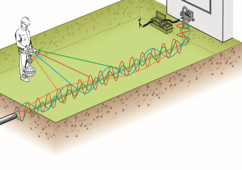
The other end of this technology is omnifrequency receiving. Omnifrequency receivers search for, detect, and process multiple frequencies, all at the same time. Their unique antennas give operators the information they need to make informed judgements about a utility’s location.
By tracing the same set of frequencies applied to a utility by an omnifrequency transmitter, omnifrequency receivers get locating professionals closer to seeing the full picture of an underground network.
Degrees of Information
The locator training program from Staking University teaches that receivers are the “dumb end” of utility locating technology.1 And it’s no surprise why: whereas a transmitter can be manipulated in a number of ways to improve locating speed and accuracy, a conventional receiver can only detect signal strength at a specific frequency. On the receiving end, it is taught, not much can be done to improve locating conditions or the traceability of the signal.
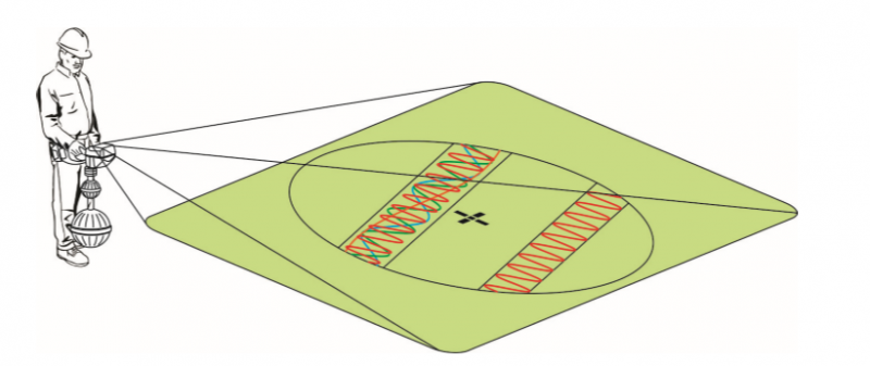
That said, the more information a receiver provides, the more useful it is. Receivers can be moved throughout an area to yield information about a signal: how strong it is, its direction, and whether it is round. More sophisticated receivers provide more information about a signal, such as depth and interference. Receivers with omni-directional antennas provide all of this information at once, including field shape.2
However, even the most advanced receivers on the market are limited to tracing one signal of a particular frequency at a time. This limitation of the technology means receivers can only reveal a fraction of relevant information about an underground network. As locating operators know, there’s a lot happening underneath, and it takes time and careful execution to locate accurately. Without the ability to trace multiple frequencies at once, professionals can only see part of the picture that makes up the underground.
Finding Assets with Omnifrequency Receivers
Omnifrequency receiving technology has the potential to result in faster locates and better information for facility owners, locators, and other stakeholders. Their ability to track multiple frequencies simultaneously means that locating professionals can see where each frequency is traveling independently. Tracing multiple frequencies can provide indications of a variety of features about not only the signal, but the underground environment as well.


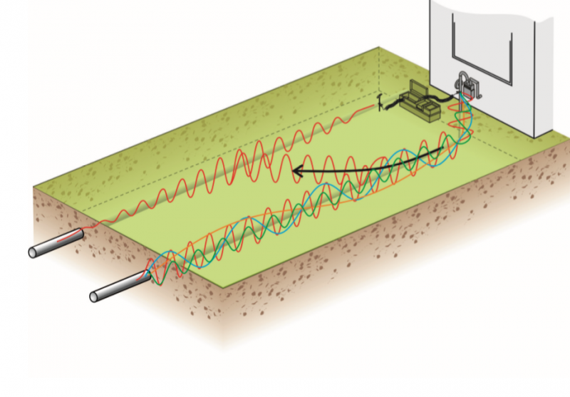
A utility energized by an omnifrequency transmitter (left) is distinguished from a parallel utility that has been energized with one frequency only (right).
Omnifrequency transmitters include different “suites” of six frequencies that range from low to high. The logic of omnifrequency receivers is the same: operators can choose from one of many suites of six frequencies to trace, including both active frequencies for use with the transmitter and passive frequencies. They are also capable of broadband receiving: frequencies from the very low to very high ranges can be traced.
In addition to detecting multiple frequencies at once, omnifrequency receivers are able to distinguish the position, direction, and orientation of signals at any of the frequencies it can trace. If two parallel utilities are energized with sets of signals at different frequencies, the omnifrequency receiver display shows two separate lines representing the two sets of frequencies.
In one experiment on locating a tee, industry publication Underground Focus writes:
A receiver cannot determine the exact location of a tee because the receiver is unable to simultaneously locate two lines. It doesn’t matter if the two lines are parallel or perpendicular, connected to each other or not. The receiver processes information and presents it as if there is only a single line running in a single direction.3
It remains true that modern receivers cannot locate two lines at once. However, omnifrequency receivers bring the industry closer to that reality.
With the ability to simultaneously track signals with many frequencies, omnifrequency receivers offer a better view into a local underground network, including tees, crossings, and other underground intersections.
Revisiting Bleed-Off and Bleed-On
Having higher frequencies on a utility means that significant bleed-off is inevitable. Usually, significant bleed-off would pose a problem with conventional locating equipment. But omnifrequency receivers leverage bleed-off to their advantage.
First, the existence of lower frequencies on a utility ensures that a well-grounded utility can still be traced, even if higher frequency signals bleed off quickly. Since omnifrequency receivers identify signal at different frequencies, tracing a target utility is as straightforward as following the lower frequencies.
Second, omnifrequency locating is less susceptible to distortion. Distortion is caused by the interaction of two or more signals at the same frequency. In conventional locating, distortion is a common issue that prevents accurate locating. With omnifrequency locating, the target utility is energized with multiple signals at different frequencies. This enables the operator to trace the different signals without distortion, lowering the risk of mis-marking the utility.
Lastly, some locates require bleed-off to be successful, and it’s impossible to know whether it will be necessary in advance. The higher frequencies in an omnifrequency suite the better the odds that line legs, crossings, tees, and laterals are energized.
Next Steps: Getting the Whole Picture
Omnifrequency receivers and transmitters offer significantly improved visibility to what’s underground. Their ability to simultaneously apply and trace multiple frequencies gives locating professionals the means to see the whole picture, pushing the industry closer to faster and more comprehensive locating.
References
- “Locating is an Art, Not a Science.” Underground Focus 28.6. Pg. 5.
- In another white paper, we explore how omnidirectional receivers perform full-field locating to calculate signal intensity, direction, shape, and interference simultaneously and from a single point in space, without having to perform peak/ null validation tests or reorient the receiver. Click here to read more.
- “Locating into a Tee.” Underground Focus 28.6. Pg. 46.
- “Transmitting Truth.” Underground Focus 28.6. Pg. 17.
- “How Locating Instruments Work.” Staking University. Published by Underground Focus. Pg. 30.
- Mitchell, Jeff Ambrose. “Waves & Frequencies.” In Introduction to Locating Buried Utilities, pg. 94. First ed. San Bernardino, CA, 2009.
- “Understanding the FCC Regulations for Low-Power, Non-Licensed Transmitters.” Office of Engineering and Technology Federal Communications Commission, pg. 5. 1996.


