Induction: An Important Locating Tool
Introduction to Induction
Induction is the process of energizing a conductor without metal-to-metal contact. It occurs when an
electromagnetic signal generated by an excited conductor induces a voltage into another conductor. In utility locating, this offers a way to energize a utility where metal-to-metal contact is not possible. Because the method of energizing the utility is different, it’s important to understand what happens during induction for locating accuracy.
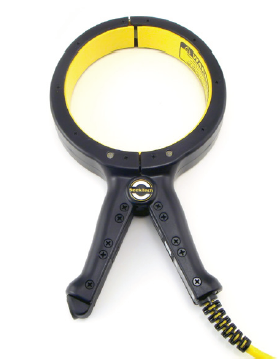
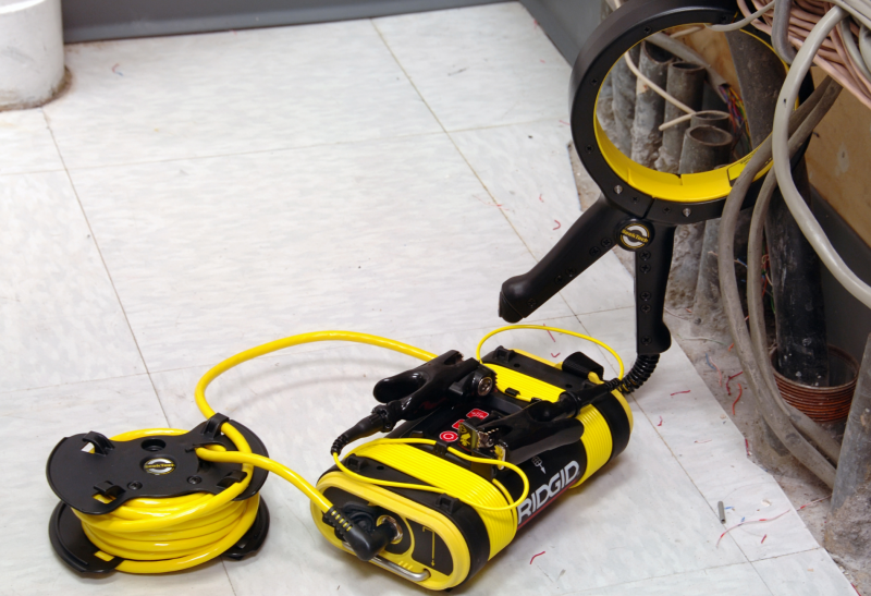
There are two ways to induce a current onto a target utility. The first method is with a clamp, or coupler. The clamp’s jaws are placed around the conductor you want to energize, and the other end of the clamp is plugged into the transmitter. The jaws put out a signal that induces a current onto the target conductor.
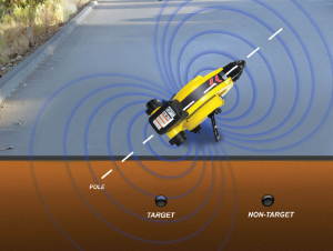
The second type of induction uses a coil built into the transmitter. When positioned over the target utility, some of the energy emitted from these coils transfers some of its energy to the utility, causing it to be energized with the transmitter’s signal.
Using Induction
Induction gives you a way of getting a signal onto a line when a direct connection isn’t possible or doesn’t give you the result you want.
Benefits of Induction:
- Energize a conductor without physically touching it.
- With proper transmitter management (placement, orientation, aiming, frequency selection, and power output) you can determine which
conductor gets the most signal and creates the best locating circuit. Induction may, in some cases, help isolate difficult (congested) circuits. - Induction can be used to sweep an area to see if any conductors are present. If the likely direction of the pipe or cable is known, two people can sweep, with one carrying the transmitter and one carrying the receiver, as they walk in tandem. If the receiver and the transmitter cross
an underground conductor at the same time it may be energized and show up on the receiver.
There are two means of inducing a signal onto a target utility: by using an inductive clamp (right) or by broadcasting a signal using the transmitter’s internal coils (left). In both cases, the signal energizes the utility for tracing.

Overcoming Obstacles
A common myth about inductive locating is that it is less accurate and more error prone than locating with direct contact. The truth is that a number of factors can influence the accuracy of both methods, but arming yourself with knowledge about the specific obstacles you may encounter can go a long way towards improving accuracy.
- Without metal-to-metal contact, a smaller portion of the transmitter’s signal makes it onto the target conductor. The resulting signal may be weak, limiting the distance you can trace the line. This is especially true with deeper conductors.
- Tip: Increase the transmitter’s power to broadcast a stronger signal, which will result in more current flowing on the utility. More current flowing on the line makes for a stronger signal to trace. Additionally, the signal induced onto a line will be strongest when the transmitter’s antenna is in-line with the conductor. Transmitter cases have arrows to help you align the unit properly.
- Induction using just the transmitter’s coils does not discriminate between utilities, either above ground or below ground. The higher the frequency, the easier it is to induce a current onto all of the surrounding utilities.
- Air-coupling occurs when the transmitter’s signal travels through open air and is received directly by the receiver. This causes the receiver to sense the signal from the transmitter when what you want is the receiver to sense the signal from the utility line so you can trace it. When you’re close to the transmitter, this direct signal is much stronger than the signal coming from the utility you’re trying to locate and it may add confusion.
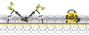
- Tip: You can test for air coupling with a receiver that has an omnidirectional antenna array. To test for air-coupling, tilt the locator about 45° toward the transmitter, with the lower antenna of the locator touching the ground. Then tilt it about 45° away from the transmitter. Observe the depth reading. If it changes significantly, air-coupling is occurring. Move the transmitter and receiver farther apart and test again until you confirm that there is no air coupling.

- Tip: You can test for air coupling with a receiver that has an omnidirectional antenna array. To test for air-coupling, tilt the locator about 45° toward the transmitter, with the lower antenna of the locator touching the ground. Then tilt it about 45° away from the transmitter. Observe the depth reading. If it changes significantly, air-coupling is occurring. Move the transmitter and receiver farther apart and test again until you confirm that there is no air coupling.
- It is more difficult to tell that you are tracing the target line.
- Tip: Trace out to a known termination point and mark the line on the way back to the transmitter. Following to a known termination point helps verify you are tracing the target conductor.
There are many scenarios when induction will be required for accurate locating. Regardless of the
method used, knowing how your equipment works, following best practices, and understanding the locating process will help set up your locates for success.


